
Haha, I can make one. If you could make up a wire schematic, I'd greatly appreciate it! Where can I get the relays from?Originally Posted by RealMcCoy


Haha, I can make one. If you could make up a wire schematic, I'd greatly appreciate it! Where can I get the relays from?
Last edited by Greg E; 08-07-2011 at 07:32 PM.
2014 Exomotive Exocet - #101 "shocker yellow" - 1.8L 5-speed 3.9 torsen FMII powered
Read more: http://mevowners.proboards.com/threa.../greg-pa-build
99 Solano Black VR4 - #16 of 287 - ground up restoration - sold
98 Pearl White VR4 #54 of 231 - 12.84@105mph - 93 Octane 12.50@107mph - 100 Octane with Chromed ECU - sold
99 Pearl White VR4 #108 of 287 - 3RD place stock car class ECG 11 - Sold
98 Black VR4: 100% stock - totalled by an Illegal 2-12-08
95 White Stealth TT - 11.852 @ 118.25 - sold
95 SSG Stealth TT - 11.981 @ 115.81mph - sold
"I don't actually work on cars, I just talk about them on the internet."

I already posted a diagram of my system:
Let me try and clarify what it is we're doing and what the diagram represents...
The relays I used were standard Bosch style relays. You can pick them up just about anywhere. They are all plainly labeled with the pin #'s 30, 87, 87a, 85, and 86.
Pins 85 and 86 are the signal circuit, when current flows through them, the relay is engaged. Pin 30 is the common high current post, when the relay is not engaged, it is connected to pin 87a, when engaged, it's connected to pin 87.
The circuit labeled "MPFI" is the fuel pump power source from the factory MPFI relay. We're using that to turn on the hotwire relays.
The circuit labeled ECU is the factory signal from the ECU to engage the resisted mode. The ECU grounds this circuit to engage the relay. We're pretty much duplicating the factory setup here.
So what we do is feed power from the MPFI relay to pin 85 on BOTH our relays, the hotwire relay pin 86 is grounded, so it automatically engages whenever the MPFI is powered up. the resistor relay pin 86 is grounded by the ECU, so it will engage when the ECU switches to non-resisted mode. The power out of the hotwire relay is split into two parallel circuits, one resisted, one not... The resisted leg is hooked to pin 87a of the resistor relay so that any time the relay is NOT engaged, you have resisted power. The non-resisted side is hooked to pin 87 so that when the ECU engages the relay, you have non-resisted power out pin 30.
This is the factory system we're replacing:
Let me know if I can clarify anything further...
Last edited by RealMcCoy; 08-07-2011 at 11:43 PM.
Thank you to whoever fixed the thread title...
After several edits and second guessing my own thoughts, I think I finally clarified my clarification.... LOL
Last edited by RealMcCoy; 08-07-2011 at 11:42 PM.
Good read, I admire the stubborn never let it beat you attitude that drives you to do the research. When I want to know something or why I got the results I did I pretty much won’t quit until I get the answer.
Good Job!
the moral of the story is, twin stock FPR's...
Maddog Performance Engineering
And two throttle bodies
Dont listen to them, you will break a ringland.
GTFO nowReally we just need ram air, that way we'll make boost with an N/A!
"Speed has never killed anyone, suddenly becoming stationary that's what gets you." - Jeremy Clarkson
I was thinking of doing something similar because I hated the noise that walbro makes when hotwired but then I bought a denso fuel pump and an afpr ..
Last edited by mb7050; 08-08-2011 at 11:46 AM.
I had 2 Walbros in parallel powered by 2 Resistor packs in parrallel, I have another Resistor so I could try 3 in parrallel I suppose.
Looked at the injector resistor pack but it doesn`t look substantial enough compared to the pump ones?.
It never dawned on me that they would inrease current draw as they slow down but it makes sense, have split many motors down before for repair so I`ve got a good understanding of what`s inside.
GTO-TT, PTE 1200's, M20, Emanage Ultimate, OS Geiken R3C,
TD04-16g`s, Maf-t. 13g`s 12.4@115mph / 16g`s 12.5@117mph.
 Posting Permissions
|
3000gt.com 3000GT / Stealth International WWWboard Archive Jim's (RED3KGT) Reststop |
|
Team 3S 3000GT / Stealth / GTO Information daveblack.net |
|
Michigan 3S MInnesota 3S Wisconsin 3S Iowa, Nebraska, Kansas 3S |
North California 3000GT/Stealth United Society of 3S Owners 3000GT/Stealth/GTO Forums 3000GT/Stealth International |
|
3S National Gathering East Coast Gathering Upper Mid-West Gathering Blue Ridge Gathering |


 Reply With Quote
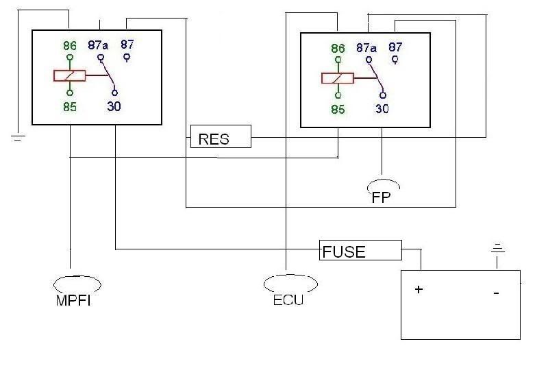


Bookmarks