
Similar reasons why piggyback tuning is so limited on these cars. Also those running MAF-T's run into similar problems that those running speed density since the MAF-T locks in baro and IAT's.


Similar reasons why piggyback tuning is so limited on these cars. Also those running MAF-T's run into similar problems that those running speed density since the MAF-T locks in baro and IAT's.
how about if you use IAT and BARO signals from those late model gm mafs or hack up the stock maf just to get IAT and BARO reading,

This is what bboyalan and I are doing with my car. I just bought a stock maf from Ground Zero Performance, we are going to hack up the stock maf and we have a pigtail for the harness to wire in to use the IAT and Baro sensor. This is going to be very nice with my GM maf and maf translator.Originally Posted by mb7050

I was looking at some data from those late model GM mafs (3.75") and I found out that the IAT sensor in those is actually very close to our IAT specs
Last edited by mb7050; 02-25-2012 at 03:21 PM.
the GM MAF frequency output should be baro and temp compensated, so there should be no need for the ecu to calculate that again
'
The stock sensor is a volume sensor, so the ecu needs temp and baro data to compensate the airflow reading.
If we connect an IAT and/or baro sensor, then we would be double compensating for the air
and then this
"If the EVO ECU can handle the GM MAF frequency range, I see no reason why direct GM MAF operation isn't possible? Futher, combining something like a Subaru MAF (hot wire 0-5V) with a voltage to frequency converter could allow a good post turbo MAF sensor solution, as the Subaru MAF has proven to be much more stable in a pressurized enviroment then the GM sensors by the Subaru community".The GM meter is a true mass airflow meter. The Mitsubishi in comparison is actually a velocity meter with a baro and IAT sensors used to calculate the mass flow rate. The GM sensor measures changes in density directly and the output reflects a "true" mass airflow. The Mitsubishi sensor outputs a frequency based on the air velocity, then the ECU calculates mass flow rate based on baro, intake temp, and MAF frequency. The caveat here is that the GM sensor also is to some extent a humidity meter as well, as humidity also affects the sensor output, where I think humidty only marignally affects the Mitsubishi sensor, if at all.
The issue with locking the baro and IAT sensors is you no longer have baro and IAT trims. While you will compensate for density changes because of these different ambient conditions, you will not get corrections that will adjust fuel and timing to accommodate these different ambient conditions.
On one hand, this SHOULD provide more stable AFRs and timing advance, provided the MAF accurately measures air mass under various ambient conditions. On the other hand, the car will not be tuned to best optimize different ambient conditions.
To take it one step further, it seems like the EVO ECU should be able to accommodate a GM MAF directly. The GM MAF uses a Frequency output. Provided the EVO ECU can accommodate the frequency range of the GM MAF, changing the MAF scaling table to match the GM MAF output should provide reliable fueling. You would want to disable any density compensation within the ECU however, which is seems like has been discovered recently.
If the EVO ECU can handle the GM MAF frequency range, I see no reason why direct GM MAF operation isn't possible? Futher, combining something like a Subaru MAF (hot wire 0-5V) with a voltage to frequency converter could allow a good post turbo MAF sensor solution, as the Subaru MAF has proven to be much more stable in a pressurized enviroment then the GM sensors by the Subaru community.
Also, I think this thread title should be relabeled as something to do with "Direct GM MAF Implementation Discussion," or something similar, as it would probably get a lot more knowledgeable people involved.
Read more at http://forums.evolutionm.net/ecuflas...ktrack=kcplink
Last edited by mb7050; 02-25-2012 at 03:40 PM.
Trevor did this years ago I wonder what was his conclusion ??
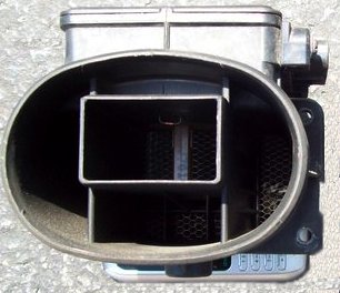
Anyone replaced the stock intake bubble with something like this ?
4" piping
3.5" piping

Last edited by mb7050; 02-25-2012 at 03:42 PM.
good read about our maf
Programming the Mitsubishi MAF in AEM
Mitsubishi uses a unique Mass Airflow Sensor (MAF) in most of its EFI cars - unique, because it isn't really a real MAF. Instead, it measures air volume, not mass.
This sensor uses a technique called the Karman Vortex Street to measure air volume. The inlet airstream passes over an airfoil. This airfoil generates vortices in direct proportion to the volue of air flowing over it, and a pressure transducer is used to count the vortices.
Accordingly, the output from the sensor is a pulsed (frequency) signal that is proportional to airflow volume. An Air Temperature Sensor (AIT) inside the sensor body is used in conjunction with a calibration table in order to correct volume for density.
On the MAF sensor used on a Stealth or 2G DSM, the sensor is capable of measuring roughly 2800 Hz of air, which corresponds to approximately 650 CFM.
On a Mitsubishi using a "MAF", what you really have is a volume, plus some corrections tables. This makes for a calibration which shares elements of a true Mass/Air system and a Speed/Density system - it is a hybrid of the two. You are less concerned about determining VE the way you are in a "pure" Speed/Density, because the volume sensor accounts for VE (you are measuring volume directly, not inferring it from Manifold Pressure and Engine RPM) but you still have to correct for air temp and air pressure.
That, however, is largely theoretical. You can treat the calibration as if it were a MAF-based system, once the air temp and baro pressure tables are set.
One immediate AEM "Weird Harold" is that the Load axis units used on the fuel map etc are completely bogus. If, for example, you set the Load units to PSI, the Load PSI will only correspond to actual manifold pressure through sheer coincidence. DO NOT believe the units! Instead, connect a real MAP sensor (see http://www.farnorthracing.com/stealth/MAP_sensor.html for more info) and use it to determine what actual boost pressure corresponds to what Load axis.
Note too that the AEM software will display the scale on all Load related tables and maps using the scale defined for your MAP sensor - in other words, if you connect a 2 BAR map sensor to the AEM, then the Load units range will be 0-2 BAR (or equivalent in PSI or kPa) even though there is no direct relation between the Load value (as measured by the MAF) and the MAP sensor.
It doesn't actually scale the Load axis - don't panic! It just scales the units associated with MAF_as_Load. This is a tie-in with speed/density mode (where MAP units really are the Load axis) and strictly speaking, it's a bug. But it only affects display, not operation. Bottom line: treat Load units as a dimensionless quantity, and treat MAP_as_Load as real units, even though the software makes them look like the same thing.
So then, the MAF sensor produces a frequency signal (in Hz) that corresponds to an air flow volume. The AEM transforms this frequency into a Load parameter which is then used as the Y axis in any number of tables. How does that work?
Firstly, there is an Option for the MAF called VMAF_Flow_Max. This option is used to determine the maximum amount of flow that the sensor can read. Note that this is a SOFT maximum, set in software, that has NOTHING to do with the actual physical flow limit of the MAF (the point where increasing air volume no longer produces an increasing signal.
VMAF_Flow_Max works in a non-obvious way which we will describe later.
The other Option that controls the MAF is VMAF_Flow_Sum_Revs, which is used to determine over how many engine revolutions the MAF pulses are counted per "timeslice" or "window" in which we calculate load. Note that the AEM works in terms of pulses, not in terms of frequency which is how most of the systems that talk to the OEM ECUs describe airflow.
So here's the description of the AEM's operation:
1.The MAF vortex pulses (and fractional pulses) are counted between a number of engine revolutions, set in option VMAF_Flow_sum_Revs, this sum is shown in parameter MAF_Flow_sum_raw
2. This is then corrected for barometric pressure and air temperature as shown in parameter MAF_Flow_sum_cor
3.MAF_Flow_sum_cor / VMAF_Flow_Max = MAF_as_Load as long as MAF_Flow_sum_cor in is the range defined by VMAF_to_TPS_Above to VMAF_to_TPS_Below
4.Since MAF_Flow_sum has a range of 0 to 4095.9, @ 6000 rpm and sum revs of 1 would give a maximum frequency of way over 100kHz.
5.Parameter T4PER will indicate the period = 1/frequency of vortex meter, expressed in microseconds.
6.MAF_as_Load is a 0-100 value indicating the percentage corrected load range of the flow meter.
7.Engine Load is the same value converted to an engineering unit.
8.The scaling for humans can be adjusted via the options MAF_scalar, MAF_offset, Load_scalar, and Load_Offset (I haven't tested this yet - it might be possible to tweak MAF units to match - or at least approximate - MAP units. Or maybe it would be better to just display 1-100)
The trick is that, unlike what it says in the manual and in the Context Sensitive Help, VMAF_Flow_Sum_Revs is CAMSHAFT revs, NOT CRANK revs.
So at a given engine RPM, divide by 2 to get cam revs. Then divide by VMAF_Flow_Sum_Revs (in my calibration, "4") to get the number of "windows" per minute in which pulses can be counted. Multiply by VMAF_Flow_Max to get pulses/min and divide by 60 to get pulses/sec (AKA Hz).
That gets you the maximum MAF frequency at that RPM that the calibration can support.
It's the at that RPM part that's so tricky. There is no timer loop in the AEM that just reads the MAF pulses and puts the current MAF frequency into a register or whatever. Instead, the program just counts MAF pulses per "window" and scales that as a 0-100% load value. (Represented as MAF_as_Load) and then further presented in engineering units (as Load)
But because the "window" gets shorter in time as the engine revs higher, the physical volume of air increases at the same MAF count at higher RPM. A count of 30 pulses in a window is less air at 3000 RPM than it is at 7000 RPM. So if the max pulses number is too low, you run out of "flow" at a low RPM.
Perhaps an example is best:
Using VMAF_Flow_Sum_Revs = 4 and VMAF_Flow_Max = 40
8000 RPM = 2667 Hz
7000 RPM = 2333 Hz
6000 RPM = 2000 Hz
5000 RPM = 1667 Hz
4000 RPM = 1333 Hz
3000 RPM = 1000 Hz
2000 RPM = 667 Hz
1000 RPM = 333 Hz
This calibration ensures that physical MAF overrun takes place at 8000 RPM - up where it is safe. But it is very easy to flow ~ 1500 Hz of air in the 4500 RPM region and hit the VMAF_Flow_Max limit. This is manifested by triggering "fuel cut" which effectively shuts the car off.
So if we change the value of VMAF_Flow_Max to 50, we get:
8000 RPM = 3333 Hz
7000 RPM = 2917 Hz
6000 RPM = 2500 Hz
5000 RPM = 2083 Hz
4000 RPM = 1667 Hz
3000 RPM = 1250 Hz
2000 RPM = 833 Hz
1000 RPM = 417 Hz
It is now possible to physically outflow the MAF starting at 6500 RPM or so (assuming the engine will flow that much air) but we bought ~400 Hz of headspace at 5000 RPM.
Given that VE starts dropping at higher RPM, this tradeoff might be worth it.
The missing piece of the puzzle at the moment is a table that equates CFM to airflow Hz. With that, one could work out an airflow demand curve and pick the value of VMAF_Flow_Max accordingly.
By using the data from http://www.stealth316.com/2-mas_liter-per-hz.htm I was able to work out a polynomial best-fit equation to approximate the Hz to CFM data from the MAF.
y = -1E-08x3 + 2E-05x2 + 0.2452x - 2.8571 if you are curious.
With that, I could equate the max Hz the AEM EMS can read at each RPM to a CFM number.
Then, using Engine Analyzer 2, I worked out some CFM demand values at various boost pressures. These numbers I don't trust very much, especially up top where I know errors in port size and camshaft specs and whatnot artificially choke flow - but the values returned in the midrange seem reasonable.
Plus, the calculated numbers for CFM I'm using are raw, not corrected for air temp and baro pressure. So there's about a 10% swing on the calibration side and a further 10%-ish swing on the calculated demand side.
But at 11 PSI, the default value of VMAF_Flow_Max should be good in most cases unless the air is cool-ish or dense. At 13 PSI, you're right in the middle of the error zone, and at 17 PSI, no way no how.
By changing VMAF_Flow_Max to 46 you reach the limit of the ECU to read increasing MAF frequency at 7000 RPM, meaning that above 7000 RPM, assuming the engine demand is there, it is possible to run out of headspace (something that is impossible with the default VMAF_Flow_Max) At this setting, 11 and 13 PSI are good to go with plenty of room. There is a danger spot at 17 PSI at 6000 RPM where demand is 560 CFM but the AEM can only read 540 CFM - but this is a case where the temp and pressure corrections work in our favour and it might squeak through.
And at VMAF_Flow_Max of 48, demand is always met, but now there is potential to run out of calibration headspace at 6800 RPM instead of 7000.
The bottom line here is that given my intent to run 16 PSI or so, changing VMAF_Flow_Max to 46 from 40 almost certainly buys me all the headspace I need in the MAF to keep me off the boost cut - and all I have to do to fix the fuel maps is multiply the entire table by 46/40 = 115%
More and updated info at ;http://www.farnorthracing.com/stealt...Mitsu_MAF.html
Last edited by mb7050; 12-09-2011 at 02:33 PM.
yes but it doesnt change the fact that the housing 'becomes "bottleneck" after 650cfm' ?...
Last edited by mb7050; 12-06-2011 at 12:05 PM.
Where is the adjuster screw on these? cus I have one apart on my desk. MAF sensor, barro and air temp all desoldered from the board. It's completely apart and there is no pot or adjuster anywere. I suspect this is changed by changing resitor values not an actual screw. Unless the plates in the lower assembly can be bridged to change the calibration/configuration.
 Posting Permissions
|
3000gt.com 3000GT / Stealth International WWWboard Archive Jim's (RED3KGT) Reststop |
|
Team 3S 3000GT / Stealth / GTO Information daveblack.net |
|
Michigan 3S MInnesota 3S Wisconsin 3S Iowa, Nebraska, Kansas 3S |
North California 3000GT/Stealth United Society of 3S Owners 3000GT/Stealth/GTO Forums 3000GT/Stealth International |
|
3S National Gathering East Coast Gathering Upper Mid-West Gathering Blue Ridge Gathering |


 Reply With Quote

Bookmarks