
Yeah I already had that . . . I also had the actual knock voltage - see my post on bawcOriginally Posted by Greg E


Yeah I already had that . . . I also had the actual knock voltage - see my post on bawc

Just so this information is here too. I dissasembled a board and it had 4 layers. The "blind via" doesn't attach to anything. I think this is conclusive.
www.Chromedecu.org
Plug and Play Flash Ecus, why use a harness when you can just Plug and Play?!
2 year Warranty on all ECUs.
A donation of every Plug and Play Flash Ecu sale goes to Greg for more software goodness.
1999 Flashed Wide body 3000GT VR4, (Its Cianci's prototype car, but don't worry I fixed that.)
How To Contact Me:
eMail: apape10@yahoo.com
3SI: Jesters Deadd
www.Chromedecu.org
Adam, burning through the board with a propane torch is hardly conclusive. The 1/2 mm traces would burn off before you even noticed them.
But I am working on the problem with several others and should have verifiable conclusive test results when I get back from the KC area.
On another note, fun with an o-scope chasing down the knock sensor circuit...
https://www.youtube.com/watch?v=pGrc...e_gdata_player
Last edited by 99 vr4; 04-18-2012 at 01:52 AM. Reason: Added info
Blind%20Via.jpgLayer%202.jpgLayer%202%20close.jpgGround%20Layer.jpgLayers%20Corner.jpgIt was butane. And there are no 1/2 mm traces in the inner layer. I was worried the inner layers would be as complex as the two outside layers. However I was pleasantly surprised that the inner layers were pretty simple. The ground layer, we will call it layer 3, was like one big block. The other layer, we will call it layer 2, had large blocks that would connect certain pins. I found pins that connected to the blocks the blind via went through and checked for continuity with the blind via. I conclusivley can say it doesn't attach to an inner layer. In fact there are many that go through the board and don't attach to an inner layer.
What he's saying is that the via may attach to those big blocky inner layer pads via tiny traces. Those tiny traces could burn off before you ever see them.
I've seen those traces on the older PCBs. They radiate out from the via like a small X. They're bigger and more visible on the older ECUs.
That's typically done to connect vias to inner power or ground planes while maintaining some thermal isolation to improve soldering flow
oh I gotcha. You can actually see some of the vias that go through the board and attach to the blocks if you look in my pictures. The knock ground pin is a perfect exacmple. Also I found pins that connected to the blocks that the blind via goes through.
On an unmolested board I checked for continuity with the blind via with at least two other pins. Those pins I know connect to the block the blind via passes through.
Am I clear about what I did? I am sometimes not the best at explaining my madness. But there is a method to it.
Yes but you sure did not prove anything except you can take a butane torch to a ecu and burn it up real good.
I guess you just don't get it...
looks like you lifted a pad or two with your torch
a little late to the party, but that's not a blind via. You rarely see blind (or buried) via's used in any pcb bc it vastly increases costs, and rarely necessary.
On a 4 layer PCB, the inner 2 layers are typically reserved for GND and VCC planes. You can see that via runs straight through a plane on both inner layers. If it connected to either you'd be able to see it with a flashlight & loupe (it wouldn't be a 6 mil trace, it'd look similar to the via on the resistors above it (R300 / R315)). Also, easy to meter it against both planes to make sure like Jester explained.
You guys posting schematics, care to post your eagle file? I'm curious to see the schematic and how much of it is mapped.
 Posting Permissions
|
3000gt.com 3000GT / Stealth International WWWboard Archive Jim's (RED3KGT) Reststop |
|
Team 3S 3000GT / Stealth / GTO Information daveblack.net |
|
Michigan 3S MInnesota 3S Wisconsin 3S Iowa, Nebraska, Kansas 3S |
North California 3000GT/Stealth United Society of 3S Owners 3000GT/Stealth/GTO Forums 3000GT/Stealth International |
|
3S National Gathering East Coast Gathering Upper Mid-West Gathering Blue Ridge Gathering |

 Reply With Quote
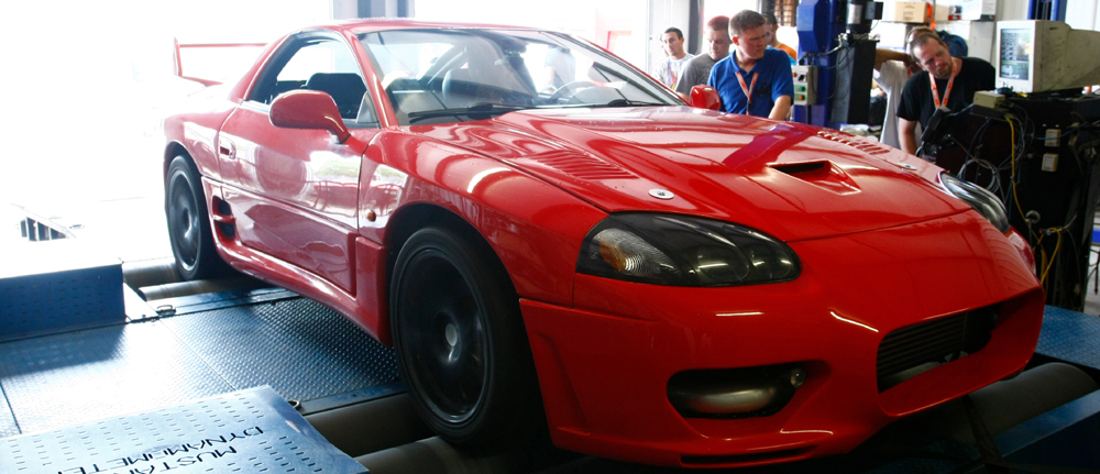


Bookmarks