Page 2 of 2 FirstFirst 12
Results 11 to 17 of 17

Thread: Wiring harness question TT ATX

  1. #11
    Now with more poop-smear Not Verified
    Join Date
    Sep 2010
    Owner Since
    Not Anymore

    Location
    Georgia
    Posts
    6,490
    Blog Entries
    3
    Thanks
    483
    Thanked 543 Times in 390 Posts
    You won't need an SAFC if you stick to stock boost. And if you use the tt harness, you'll have a resistor pack, not individual resistors.

  2. #12
    Forum User Not Verified

    Join Date
    Sep 2010
    Owner Since
    2004

    Location
    Cape Girardeau
    Posts
    4,791
    Thanks
    365
    Thanked 296 Times in 214 Posts
    I was about ready to do this and backed out due to some concerns, but it doesn't look all that hard. I was going to run a TCU, although now I would probably try to convince the aem to shift the car.

    BigTyla had some really good info on this on the other site from 2007:

    "
    Quote Originally Posted by BigTyla View Post
    After a ton of testing and countless hours beating my head on a table, I've finally finished experimentation with the TT ECU in my ATX TT conversion. And really, it's quite simple. The hardest part was figuring out what to do with the park/neutral position switch wire. After that the car ran miraculously.

    I'm going to tell you exactly how you can put a TT ECU in your ATX car if you choose to do a TT conversion. This will allow you to run your conversion with only ONE oxygen sensor, without any wiring outside of the car (besides what it takes to extend your old sensor to the rear o2 housing)! Note that my conversion was for a 1G ATX car, and I used a 1G TT ECU. I see no reason why this can't work for later generations as long as you use the respective TT ECU for your generation and cut and splice the same wires I'm about to describe. But again, do this at your own risk if you are not a 1G! I'm not sure just how different the ECU pin assignments are between generations. However, I will name each pin so that you can cross-reference for yourself, and I'll also specify which pin designations are only for the TTs.

    The following link to stealth316 will help you find out which wire is which: http://www.stealth316.com/2-ecu94.htm. If you are not a 1G and wish to try this modification, your best bet is to research the difference between your current n/a harness and the TT ECU you are going to use in your conversion and make the same modifications I am about to describe.

    1) Buy a wiring harness adapter from here: http://www.autosportwiring.com/mitsubishi.htm

    2) Find the pins on the TT ECU for the front and rear oxygen sensor, and the one wire on your n/a wiring harness for the rear oxygen sensor (for the 1G, this will be pins 55 for the front bank and 56 for the rear). Cut the wire designated for the front oxygen sensor and splice it in to the wire designated for the rear oxygen sensor. This allows you to simulate an o2 reading from both banks, even though you are really only getting a reading from the rear oxygen sensor!

    3) Cut the following wires:
    Reduce torque execution (pin 7 for 1G)
    Fuel Pump Relay 2 (pin 21 for 1G; this is a TT wire only)
    Active exhaust control unit (pin 102 for 1G; this is a TT wire only)
    Turbo wastegate solenoid valve (pin 105 for 1G; this is a TT wire only)
    Induction valve closed (pin 109 for 1G)
    Induction valve opened (pin 110 for 1G)
    Induction valve position sensor 1 (pin 111 for 1G)
    Reduce torque request 1 (pin 116 for 1G)
    Reduce torque request 2 (pin 59 for 1G)
    Starter relay signal, A/T only (pin 71 for 1G)

    It is imperative that you cut the starter relay signal wire! This wire goes into a pin in the TT ECU designated for a chassis ground, and you will short out that pin if you do not cut this wire! Note that I left the park/neutral position switch wire alone. This wire is now going into an input in the TT ECU designated for the starter relay signal. The car will still start as normal. Without the p/n position wire going into this input, the car will have very erratic timing when you shift into drive. I learned this the hard way, and it took me weeks to figure out the reason behind it.

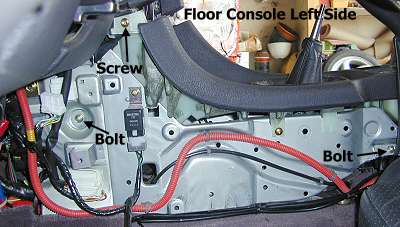
    4) Ground the wire for the chassis ground (pin 71 for 1G) coming out of the ECU side of your adapter. The best way to do this is to crimp male and female connectors on this wire and make an extention long enough to use the mounting point for the relay on the driver's side of your center console as a ground. The relay is the black box in this picture.

    Credit given to www.stealth316.com for the picture.

    5) Cap all of the wires you cut to ensure they don't short out on something, and install your wiring harness adapter and TT ECU. Then start it and be happy!

    Hopefully this will be a great asset to you guys wanting to TT your ATX.
    "

    Parting 6 speed
    Pampena 3.5 Stroker, GTX 2867 Gen IIs, AEM Series2, oohnoo SMIC, DN Hardpipes, FIC 1650s, Walbro 525, aermotive fpr, Dejon intake pipes, Tial Q, Koyo Rad, Samco Hoses, Stoptech 332mm fronts, HKS GT4 Coilovers, Spec 4+ LW, JDM 6 Speed, Billet shift forks, Pampena brace

  3. #13
    Forum User Not Verified

    Join Date
    Sep 2010
    Owner Since
    2004

    Location
    Cape Girardeau
    Posts
    4,791
    Thanks
    365
    Thanked 296 Times in 214 Posts
    Quote Originally Posted by Benjamin View Post
    Okay I feel really stupid right now. I have noooo idea why I typed TT ATX. I have a 5 speed manual transmission. I'm sorry about all that confusion. That being said I can run a safc and be okay for the time being?
    didn't see you were manual. Oh well, my re-post may help someone.

  4. #14
    Forum User
    Join Date
    Feb 2013
    Owner Since
    2012

    Location
    California
    Posts
    59
    Thanks
    14
    Thanked 0 Times in 0 Posts
    Quote Originally Posted by Benjamin View Post
    Sorry for the late response. So I can find a 96 TT Ecu, and basically cut a few wires a and it will work? I definitely wanna try this. That being said, if I do this is a SAFC still required? So I can run it on NA impedance. I can add the resistors no problem. But if what you're saying is correct then it will make my life so much easier.
    Yes that will be the easy way, you will need to cut the wires for the 6 injectors and put a resistor between the spliced wire, also cut or disconnect your VICS motor and all the ATX Stuff (if still present), TT and NA from OBD2 have the same connector style (4 plug), just make sure to swap/ignore the corresponding wires, I made a few diagrams but thats for 91-95, I have a 96 diagram but I'm still unsure about some pins.

  5. #15
    Forum User
    Join Date
    Feb 2013
    Owner Since
    2012

    Location
    California
    Posts
    59
    Thanks
    14
    Thanked 0 Times in 0 Posts


    This is 96-97 TT ECU, I need the EGR Temp pin, can't find anything about that, if you decide to do the harness mod, let me know if you find another wire so I can also add this to the wiki.
    Last edited by reses; 04-20-2016 at 08:57 PM.

  6. #16
    Forum User
    Join Date
    Jan 2016
    Owner Since
    2015

    Location
    North Carolina
    Posts
    9
    Thanks
    0
    Thanked 0 Times in 0 Posts
    Quote Originally Posted by reses View Post


    This is 96-97 TT ECU, I need the EGR Temp pin, can't find anything about that, if you decide to do the harness mod, let me know if you find another wire so I can also add this to the wiki.
    Okay Yeah I'll definitely try this. If I figure out your matching pins I'll let you know. Can you give me a guestimate on which number wires I will be deactivating?

  7. #17
    Forum User
    Join Date
    Feb 2013
    Owner Since
    2012

    Location
    California
    Posts
    59
    Thanks
    14
    Thanked 0 Times in 0 Posts
    I think that just 4 pins, those are for the VICS system, But I think that if you just leave it disconnected it will work fine (Turbo meter signal its the one that could kill some circuit when grounded)

Bookmarks

Posting Permissions

  • You may not post new threads
  • You may not post replies
  • You may not post attachments
  • You may not edit your posts
  •  
The 3000GT/Stealth/GTO Web History Project
3000gt.com
3000GT / Stealth International WWWboard Archive
Jim's (RED3KGT) Reststop
3000GT/Stealth/GTO Information and Resources
Team 3S
3000GT / Stealth / GTO Information
daveblack.net
3000GT/Stealth/GTO Clubs and Groups
Michigan 3S
MInnesota 3S
Wisconsin 3S
Iowa, Nebraska, Kansas 3S
North California 3000GT/Stealth
United Society of 3S Owners
3000GT/Stealth/GTO Forums
3000GT/Stealth International
3000GT/Stealth/GTO Event Pages
3S National Gathering
East Coast Gathering
Upper Mid-West Gathering
Blue Ridge Gathering